
Fabrication of steel structures
Steel structure is a type made of steel used for bearing in construction works. With long-term experience in the field of steel structure manufacturing, Tam Long Company has built and implemented the following processing process:
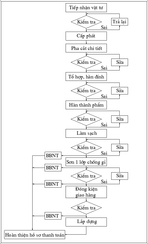
1.1. Technological process diagram
1.2. Check materials
- The manufacturer recognizes the types of materials required by the designer and must have a clear origin, certified CO / CQ materials.
- The content of material inspection is carried out according to the following requirements:
* Check certificate of origin, material origin.
* Standard geometric dimensions: Measure test by meter ruler, pair ruler.
* Surface: Convex, concave, pitting, rust, cracked, curved, warped.
* Technical characteristics of materials: steel materials, welding materials
- Types of steel used for manufacturing include:
* Steel plate according to project standards.
* Steel shape according to project standards.
* Auxiliary materials for processing work: welding materials, paint materials, other auxiliary materials ...
-All the above materials are closely monitored and controlled with specific data according to the summary of supplies. The materials are evenly divided among manufacturing areas / workshops after completion of acceptance work.
1.3. Manufacturing steps (Illustration of the cultural house of the East Country - Hai Duong province).
The typical steps for manufacturing a steel frame structure of M1 and M2 roof.

Figure 1. Roof structure M1
1.3.1. Technology plan.
* Up to processing and fabrication plans for roof steel structures M1 and M2.
- Based on construction methods at the construction site to separate frames and beams into details and detail assemblies for processing in accordance with erection measures (Figure 1).
- The main beams are fabricated seamlessly, the connecting positions according to the erection method drawings, the bonding positions are linked together by bolts by the measure code plates.
- All of these connection points after erection, alignment, and inspection are satisfactory to be supplemented by welding at the site.
* The main girder is made from steel shaped H500x300x11x18.
+ Main girder is composed of 2 beams H500x300x11x18, linked together by cross-bars, vertical bar H200x200x8x10, forming a girder frame, the positions linked together through an intermediate code sheet, the link position is Combined by bolts and welding.
+ 2 beam head frames are drilled to be connected with reinforced concrete by anchor bolts.
+ At the joint position of the main beam with the extra girder, welding the code plates into the main beam frame, linking the measure with bolts and welding together after calibration.
* The main girder and sub-girder are processed from shaped steel and sheet steel.
+ Shaped steel is the girder body and the connecting bars form a beam frame.
+ Cut details according to drawing size.
+ Processing and manufacturing each loose detail.
+ Combination of beam frames on a flat platform.

Figure 2: Split the cluster on the main beam
1.3.2. Steps of typical beam manufacturing technology M1-K2-6.

Figure 3: Beam location M1-K2-6
Step 1: Get the stamp, cut the details according to the cut phase drawing and manufacturing drawings
- Prepare.
- Documents, records, detailed drawings of the project.
- Manpower, equipment for construction.
- Supplies of the project, including steel plates, shaped steel.
- Material samples to ensure technical requirements required by the investor.
- Construction bases: Cut phase drawing, manufacturing drawings ..., ...
- Cut phase drawing is drawn, programmed on sigmanet software by mechanical engineers of the contractor's design department.
.png)
Figure 4: Cutting programming on sigmanet software
(For buffer codes, the link code is steel plate)

Figure 5: Structure of beam M1-K2-6
- Perform
- Carry out detailed classification according to drawings of beam structure M1-K2-6, including details of steel and sheet steel.
- Steel sections details: including main girder (L-8) I500x300x11x18, reinforcement bar H200x200x8x12 (H-42, H-43, H-44 ...).
- Shaped steel is cut to size, number of cut phase drawings.
- Steel plate details: including bonding plate, intermediate code of PL20 thickness and various profiles, cut by CNC machine on sigmanet software.
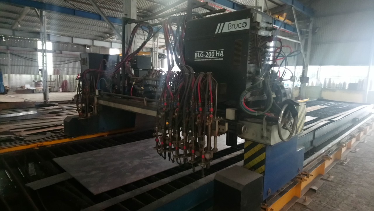
Figure 6: CNC cutting machine
1. Implementation of manufacturing main beams (L-8) H500x300x11x18.
+ Cut L-8 according to drawing size = 12325mm, L-8 is connected from 2 beams with L1 = 2500mm, L2 = 9825mm.

Figure 7: fabrication of L-8 beams
- Slice the beam with a gas cutting torch and cut the plasma, cutting along the mark on the beam.
- Cutting lines are cleaned with a hand-held grinding machine.The process of marking and cutting of construction
- eams is strictly controlled in size by the construction techniques and QC of the construction teamhà thầu.
2. Manufacturing H-42, H-43, H-44 anti-slant rods.
- Cut the bars from beams H200x200x8x10x12000mm according to the fabrication drawings and the number of cutting phase lists.
Slice the beam with a gas cutting torch and cut the plasma, cutting it according to the mark on the steel plant.
Cutting lines are cleaned with a hand-held grinding machine.
Use maintenance (cutting diagonal lines) for mass impression.
The process of marking and cutting of construction teams is strictly controlled in size by contractor's construction techniques and QC.
3. Implementation of intermediate plates from PL20.
All pads are programmed and cut by CNC cutting machine according to the profile of the details at the link button of the beam assembly
The details after cutting are numbered, name and blunt edge.
Transfer the code to the hole drilling unit.
The entire drill hole on the code is drilled by the drilling machine, magnetic drill and hole puncher at the workshop.
The entire process of cutting and drilling holes is regularly checked and closely monitored by contractor's construction techniques and QC.

Figure 9: Details of typical intermediate plate
- Request
- The details after cutting must include the detailed name according to the drawing.
- QC checks the specifications before transferring another stage.
- The whole process of checking and acceptance of the stage must have a log of details.
- Size difference is not larger than size according to table 3.12.
- Eliminate details that do not meet the technical requirements.
Step 2: Classify details, chamfer details.
a. Prepare.
- Drawings of details.
- List cut details.
- Minutes of acceptance and transfer.
- Experienced sealer, mechanic> 4/7.
- Plastma cut turtle.
b. Perform.
- The details after CNC cutting will be classified, transferred to the chamfered area, blunt edge (for non-beveled parts), here the work will be done by the chamfering team. plastma turtles and blunt edges with hand-held machines, details after finishing will be checked by QC for detailed dimensions, beveled corners and beveled hygiene.
- Satisfactory details will be transferred to the next stage.
- Unsatisfactory details will be reprocessed or removed if unsatisfactory.

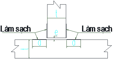
Figure 10: Blunt edge edge for L-8 girder belly reinforcement
Beveled edge of the main girder I500x300x11x18. (Beveled edge of the girder according to the ceramic welding method)
- Chamfer the beam connection points.

Figure 11: How to chamfer the connecting beam position
- Request.
- Chamfering according to the beveled edge of each specific detail of the drawing.
- The sharp edge must be round and the radius is no longer sharp.
- The chamfer must be uniform, without concave convex defects.
- QC check before moving to the next stage.
Step 3: Assembly and welding of beams K1-K2-6.
a. Prepare.
- The sealer has a craftsman> 4/7.
- Themed workers are trained in operating combination machines.
- Drawings and drawing drawings.
- The details are chamfered and cleaned before moving.
- Minutes of checking and taking over steps (According to the quality management process of the company)
b. Perform.
- The details after cutting, chamfering and acceptance will be transferred to the enclosed area. Here work is done by teams that assemble and assemble details into detail assemblies.
- Details and attached detail assemblies will be checked by QC for dimensions, weld joints, weld joints, measures for reinforcing deformation when welding, when details and detail assemblies are satisfactory move to the next stage.
|
Location |
Specification |
Tolerances |
|
Combination of T-beams |
|
e < 3 / a> 100. However, when e is over 2mm increase leg length ey e. |
|
Combination of edges |
|
e <3 , a> 100, c > However, when e is over 2mm increase leg length ey e. |
|
Welded edges (without porcelain lining) |
|
t <15mm, e <1.5mm, a >100 e < t/10 However , e < 3
|
|
Other details |
|
SMAW 0 < e < 4mm SAW 0 < e < 2mm. FCAW 0 < e <3mm GMAW 0 < e < 3mm |
|
Welded edges (Porcelain lining) |
|
|
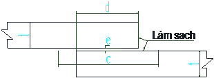
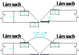
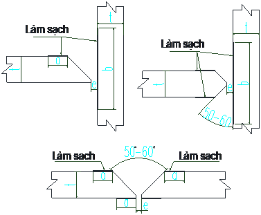

Standard table beveled edges and assembly gap

Figure 12: Assembly drawing of beam beam K1-K2-6
Figure 13: Details, assembly specifications of beams K1-K2-6
- Perform:
+ Carry out assembly L1 and L2 for I500x300x11x18 (L-8) Main girder.

Figure 14: Connecting L-8 beams to beam blocks K1-K6-6
+ Welded joints are ceramic welds.
+ Beveled corner, joint gap, joint cleaning according to the standard of joints.
+ Put 2 beams together.
+ Adjust the total size and size of welding gap according to standards.
+ Use comb tooth codes to fix 2 beams together.
+ At the end of the welding line, assemble the code plate with the same thickness.

Figure 15: Specification of fixing joints and reducing welding stress
3. Request
- The welds must meet the technical requirements and meet the requirements for the welding process.
- Clean welds and weld deformation bars before welding officially.
- The plate and the wing plate after assembly must check the straightness.
- Two-way eccentricity between 2 connecting beams is + 1.5 mm.
- Weld gap is 8 - 10mm.
- QC check before moving step.
Step 4: Welding the L-8 beams for beams of K1-K2-6
a. Prepare.
- Welder skilled workers> 5/7.
- Welding wire of the project.
- Welding and equipment for welding process.
- Adjust the welding power according to the welding standard table
- For this girder, there are belly and wing thicknesses of 11 and 18mm.
b. Perform.
Solder layer 1 with semi-automatic welding machine.
Welding finishing grades 2 and 3 with automatic welding machine.
Transfer details to the mold of the port welding machine.
Align position, current, speed ...
Perform structural welding under anti-deformation welding scheme.
.png)
Parallel welding parameters table

Figure 16: Sequence of welding seams
(Note: The welding process flips the beam to ensure that the welding line is always welded in the welding position)
- Request
- Welds are not airy, puffed.
- Welds have no defects.
- The weld must be both beautiful and aesthetic.
- Correct welding height.
- Guaranteed requirements when ultrasound.
Step 5: Cluster of detailed beams M1-K2-6.
a. Prepare.
- The assembler has a mechanic level> 4/7.
- Flat floor, equipment for assembly.
- The assembly details have been prepared from step 1 to step 4.
b. Perform.
Marking the position of the drill hole, the welding position linking the intermediate plate and the details of the beams to the beams, L-8 girders of the beams M1-K2-6.

Bản vẽ lấy dấu và bảng tổng hợp chi tiết của dầm M1-K2-6

Drawings of coordinates of hole centers and associated locations

Drawings of coordinates of hole centers and associated locations
- Drill holes for connecting bolts according to hole specifications.
- Insert the cushion plates into the assembly position
- Welding firmly with cushioning plates with L-8 beams,
- Get detailed markers H-42, H-43 and H-44 on the mattress.
- Mounting the details on the cushion and welding (The welding must be sure to move, rotate the beam).
- Additional anti-roll measures can be used to make sure the mounting and welding process without distortion compared to the drawing.

c. Request
- Installation deviations according to assembly standards of technical requirements.
- The degree of non-perpendicular detail with each other <1.5mm.
- Clean welds with hand-held grinding machines.
- QC inspects specifications and specifications according to the requirements of the drawing before changing the welding step.
Step 6: Welding finished parts by semi-automatic welding method.
a. Prepare.
- Welders are skilled workers> 5/7, and are trained to use and operate port welding machines.
- Welding wire for welding according to technical requirements.
b. Perform.
- Welding intermediate code plate with L-8 main girder body
- Welding struts with intermediate code sheets
- Align position, current, speed ...
- Perform structural welding under anti-deformation welding scheme.
c. Request.
- Welds are not airy, puffed.
- The weld reaches Δ according to the welding portion of each position.
- The weld must be cleaned after welding.
PERFECT WELDING PROCESS AND NON-CANCELED CHECKING
Step 1: Implementation
- The welding methods used are: manual welding, semi-automatic welding, automatic welding.
- Welding work performed by welders with a skilled certificate.
- All welds will be tested 100% externally.
- Welds will be inspected without destruction as required.
- Non-destructive testing method is MT, UT
- Size test is done after welding when finishing,
- Product dimensions must ensure the required dimensions in fabrication drawings and allowable tolerances.
- Records of acceptance are established according to the requirements of the project
Step 2: Combine the truss test.
- With equipment and products after manufacturing and mechanical processing, it is required to carry out the complex at the workshop to fully check the dimensions such as required drawings and permissible errors before handing over to the construction site. The main items of the test combination include: the main girder frame.
- Records of acceptance are established according to the requirements of the project.
Step 3: Close the package
- Packing products is a step to ensure that the goods are safe in the frame, helping the crane move, loading goods onto safe means of transport.
- The method of packing bales is to use box-shaped, box-shaped bales, etc.
PROCESS OF TEST COLLECTION
- Check specifications and quantity of all details and detail assemblies according to drawings.
- Check the thickness, length, width of the part.
- Check the size shape and different hole positions according to the drawing.
- Check material surface and deformation of material surface due to welding process.
- Check that the weld positions are repaired due to faults while checking the concave convex deformation of the material after processing.
- Check at the joint locations.
- Check specifications, weld dimensions according to standards, suitable for each position of welding seam.
- Check for defects of welding seams and welds.
- Check defects at the foot position of all weld lines.
- Check slag, pitting around the hole and check the gap of the holes with each other.
- Check for defects on the surface of details.
- Check the location of material deformation due to welding at the positions that link the assemblies together.
- Check the height of details, detail assemblies, detailed shapes.
- Detailed dimensions according to drawings, allowable tolerances according to standards (unless otherwise specified by the investor).
- Testing Allowable errors on all dimensions are + 2mm.
- Details of the main beam deformation curve should not be greater than L / 1000.
- The rest of the warped parts cannot be larger than L / 500.
- Size of permissible error length + 1mm.
PROCESS OF CLEANING SON
Clean components at the factory
- The components after being tested and processed, will be gathered to prepare for the cleaning by firing balls. All components are numbered according to the drawing name to distinguish, and make a list for 1 shot cleaning.
- Components are transferred into cleaning, cleaning workshops with cranes, forklifts, and gears. Make sure not to affect the size of the specifications of the structure.
Components are cleaned of the entire surface according to the standards of the construction.
Acceptance work was carried out after the components were completely cleaned.
Quality management staff (QC), perform a visual inspection of all components implemented. Make a list of components and an invitation to check with the Supervisor.
Satisfactory components are transferred to the preparation area for primer work.
Clean the surface at the construction site
Applied to painted structures. The components are painted at the construction site, due to objective reasons in the process of assembling transport planning ..
Remove oil, grease on the surface thoroughly with appropriate neutral industrial detergent or other suitable methods. In case the surface is dirty due to objective factors, it must be cleaned with high pressure fresh water. Other impurities such as dirt must be removed before painting.
For the location of paint peeling off, be treated by manual method. Surface roughness needs to be painted, cleaned and properly painted. Perform multi-layer paint, check to ensure sufficient thickness of paint required.
The application of paint is done by spraying machine, only paint brush / brush applies for angled mending work, the position cannot be accessed by paint sprayer or repair work.
Preserving paint
The paint must always be stored in a well-ventilated place, not in direct sunlight or other electrical sources. Only open paint cans immediately before painting. The paint must be mixed in accordance with the manufacturer's specified ratio. should avoid mixing paint in small parts.
The process of painting
- Satisfactory cleaned components are transferred to paint or outdoor paint yards (with good weather conditions).
- The inspector will make a list of the components to be painted. To control components and paint color format for components.
- The same paint components will be arranged in one area.
- The component is placed on a rack, 0.5m to 1.2m higher than the ground, ensuring no dust or impurities on the surface during the painting process. The structural supports, must ensure safe and durable. The exposed surface must be small. Make sure the entire surface is painted directly without moving components.
- The component is re-cleaned with compressed air before applying paint.
- Paint type and thickness of the paint according to the instructions of the construction requirements.
- Painting work must be done by high pressure sprayer, only brush / brush application for edge patching work, but not accessible by spraying machine.
Tin nổi bật
-
-
CÔNG TY CỔ PHẦN XÂY DỰNG TAM LONG MỪNG SINH NHẬT...
Ngày 08/12/2024
-

-
Công ty cổ phần xây dựng và thương mại Tam Long...
Ngày 31/08/2024
-
-
TUYỂN NHÂN VIÊN
Ngày 04/08/2024

